

How To Increase Motion Sensor Sensitivity


Now when the PIR detects motion, the output pin will go "high" to 3.3V and calorie-free upward the LED!
Once you accept the breadboard wired upwards, insert batteries and wait thirty-60 seconds for the PIR to 'stabilize'. During that time the LED may glimmer a little. Wait until the LED is off and so move around in front of it, waving a hand, etc, to see the LED light up!
Retriggering
At that place'southward a couple options you may take with your PIR. Kickoff up nosotros'll explore the 'Retriggering' option.
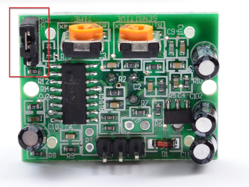
In one case you have the LED blinking, await on the back of the PIR sensor and make sure that the jumper is placed in the L position every bit shown below.


At present set up the testing board again. You may find that when connecting upwardly the PIR sensor every bit above, the LED does not stay on when moving in front of information technology but actually turns on and off every 2d or and so. That is called "not-retriggering".

Now change the jumper and so that it is in the H position. If you ready the test, you will discover that now the LED does stay on the entire time that something is moving. That is called "retriggering".

(The graphs above are from the BISS0001 datasheet, they kinda suck)
For most applications, "retriggering" (jumper in H position every bit shown below) way is a footling nicer.
If you need to connect the sensor to something edge-triggered, you lot'll want to set it to "non-retriggering" (jumper in 50 position).
Irresolute sensitivity
The Adafruit PIR has a trimpot on the back for adjusting sensitivity. You tin adapt this if your PIR is too sensitive or not sensitive enough - clockwise makes information technology more sensitive.

Changing Pulse Time and Timeout Length
There are two 'timeouts' associated with the PIR sensor. One is the "Tx" timeout: how long the LED is lit subsequently it detects motion - this is easy to adjust on Adafruit PIR's because in that location'south a potentiometer.
The second is the "Ti" timeout which is how long the LED is guaranteed to exist off when there is no move. This one is not easily inverse but if you lot're handy with a soldering iron it is within reason.
First, lets have a look at the BISS datasheet over again

On Adafruit PIR sensors, at that place'due south a little trim potentiometer labeled Time. This is a 1 Megaohm adjustable resistor which is added to a 10K serial resistor. And C6 is 0.01uF and then
Tx = 24576 ten (10K + Rtime) x 0.01uF
If the Rtime potentiometer is turned all the way down counter-clockwise (to 0 ohms) so
Tx = 24576 x (10K) x 0.01uF = 2.5 seconds (approx)
If the Rtime potentiometer is turned all the way up clockwise to 1 Megaohm then
Tx = 24576 x (1010K) x 0.01uF = 250 seconds (approx)
If RTime is in the centre, that'd be virtually 120 seconds (two minutes) so you tin tweak it every bit necessary. For example if yous desire motility from someone to turn on a fan for a minimum of one infinitesimal, gear up the Rtime potentiometer to about 1/4 the way around.
For older/other PIR sensors
If y'all have a PIR sensor from somewhere else that does not accept a potentiometer adjust, you can trace out the adjustment resistors this mode:

Determining R10 and R9 isnt also tough. Unfortunately this PIR sensor is mislabeled (it looks similar they swapped R9 R17). You can trace the pins past looking at the BISS001 datasheet and figuring out what pins they are - R10 connects to pin iii and R9 connects to pin 7. the capacitors are a niggling tougher to decide, just you can 'reverse engineer' them from timing the sensor and solving!
For instance:
Tx is = 24576 * R10 * C6 = ~1.2 seconds
R10 = 4.7K and C6 = 10nF
As well,
Ti = 24 * R9 * C7 = ~1.2 seconds
R9 = 470K and C7 = 0.1uF
You can alter the timing past swapping dissimilar resistors or capacitors. For a prissy tutorial on this, see Keith's PIR hacking folio.
This guide was first published on Jan 28, 2022. Information technology was last updated on Jan 28, 2022.
This page (Testing a PIR) was final updated on Apr 19, 2022.
Text editor powered by tinymce.

How To Increase Motion Sensor Sensitivity,
Source: https://learn.adafruit.com/pir-passive-infrared-proximity-motion-sensor/testing-a-pir
Posted by: allenbutia1993.blogspot.com
0 Response to "How To Increase Motion Sensor Sensitivity"
Post a Comment